|
|
Designing a Museum Store |
This is a slightly altered version of an article published in the postprints of a course in the design and management of museum storage, held at the Museum High School in Sorø, Denmark, October 2004 (Magasinbygningens fysik og funktion, edited by Maj Ringgaard et al., ISBN 87-990583-0-8, pp 41-43).
An analysis of the north European climate and of the preservation requirements of typical museum objects suggests a suitable low energy method of air conditioning a museum store designed to hold relatively durable materials: outside air is sucked in when its water vapour content is unusually low, while the temperature is raised slightly to give a relative humidity not far below the limit for biological growth. This combination gives a low degradation rate for both objects and the building that encloses them.
The architecture and services of a museum store should be influenced, and cheapened, by freedom from the need to satisfy human environmental needs, because people are seldom there. The museum store is a mausoleum, full of dead things whose environmental requirements are utterly different from those of mankind. Some reader will immediately interject that a museum store should be open to visitors, certainly to scholars. Libraries, in particular, reward the browser as much as the reader who knows exactly which book to order from the stack. We have to decide the priority: the object is in the store all the time, the human for brief intervals. In this article we take the object's part.
This is a long overdue innovation. Look in all the handbooks on museum environment and you will see that the recommended conditions are a hair's breadth away from what suits us humans: 18-25°C and 45-55% relative humidity (RH). Only film has a recommended storage temperature well out of the tolerance range of humans. For general museums, the temperature requirement is blatantly chosen to suit us and the RH requirement is a compromise based on a fairly superficial interpretation of chemical and physical studies of the durability and dimensions of water sensitive materials. It turns out that 50%RH is fine for humans, giving a minimum time of viability for many airborne pathogens. For objects it is not so obvious that 50%RH is optimal. Recent attempts to design standards that are more suited to the object have tended to favour a low RH, down to 25% in some photographic preservation standards. However, integrating the possibilities of air conditioning technology with the needs of the object suggests that a low RH is not necessarily a good thing.
I begin with a look at the basic environmental requirements to ensure the maximum durability of inanimate objects. During this review we will always have in the back of our minds the engineering and architectural consequences of these requirements. This multidisciplinary approach will throw up some surprises.
Museum objects are of great diversity in chemistry and construction. We have to start somewhere. First let us look at the requirements of that large fraction of artifacts that are made from hydrolysable organic materials: paper, plastics, skin and textiles. In the 1980s, Don Sebera, a chemist at the US National Archive in Washington DC, hit on the idea of expressing the environmental damage rate as lines of equal deterioration laid on a graph with temperature and RH axes. Figure 1 is Sebera's graph.
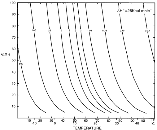
Figure 1: Don Sebera's diagram showing `isoperms'. The isoperm is a line of constant chemical durability in temperature-relative humidity space, with an arbitrary durability of unity at 50% RH and 22°C (1).
The lines of equal damage can intuitively be explained in this way: increasing temperature speeds most chemical reactions, so the deterioration rate increases towards the right side of the diagram. In a hydrolysis reaction, water is added to the reacting substance and this process is accelerated by increasing water availability, which is represented by the relative humidity. Reaction rate will therefore increase towards the top of the diagram. Combining these influences will give an increasing reaction rate diagonally towards the top right corner of the diagram. Lines of equal damage rate will be perpendicular to this direction of increasing damage, ranging roughly from bottom right to top left. The exact curve of the lines shown on the diagram is defined by a more rigorous mathematical derivation, which is described in detail by Sebera (1). Another derivation, which gives very similar results, is described by Padfield (2).
It seems obvious that we should be pushing the storage environment standard towards the bottom left corner of this diagram. Before doing that, it behoves us to check for other limits to the allowable climate. At very high RH, above 70%, there is a risk of biological degradation. At very low RH, below 25%, there is a risk of mechanical damage due to shrinkage stresses in composite materials, such as veneered furniture. These upper and lower limits are not directly comparable with the lines of equal reaction rate, because mechanical damage can occur within minutes of a low RH being established. Mould growth takes only a few weeks to establish at 70%RH, only a few days at 95%. These upper and lower limits for RH are therefore of more immediate importance to conservation than the slow acting chemical degradation. As a final complication, the RH dependence of metal corrosion reactions is complicated by the inevitable presence of water soluble salts, which begin to absorb water from the air at a specific value of RH, above which they provide a film of watery liquid which vastly accelerates metal corrosion reactions.

Figure 2: The Isoperms of Sebera, slightly revised and re-labelled to show reaction rate, form the grey background pattern. The nearly horizontal lines show the maximum and minimum allowable RH. The oval feature is an approximation to the course of the monthly running average climate in Copenhagen. The dewpoint lines show the path of air which is warmed to reduce its RH. Note that these lines cross into a region of higher decay rate as the RH is lowered (click on the diagram to enlarge it).
Figure 2 unites some of these durability considerations, and climatic factors, in a wondrously complicated diagram which shows just about all one needs to understand to design the climate controlling mechanism of a museum store. The isoperms of Sebera, slightly revised and re-labelled to show reaction rate, form a striped leitmotiv in the background. On these is superimposed an upper limit, above which microbiological decay becomes a distinct risk. This is taken from Martin Krus (3). The RH limit below which mechanical damage is likely is less firmly grounded in experiment and definitely varies with different types of art. An elegant explanation of how to derive a reasonable lower safe limit for RH from mechanical properties is given by Erhardt et al. (4).
The approximate monthly running average of the Copenhagen climate is shown as an oval ring towards the top of the diagram. This ring, which is typical for many places in northern Europe, uncomfortably straddles the limit for biological growth. Any design for a museum store in this region must ensure that the RH is at least dragged below this line.
A common way of reducing the RH in temperate climates is to warm the building, not enough for human comfort but to pull the RH down from the biologically hazardous region. This is called 'Conservation Heating' to distinguish it from comfort heating. Warming causes the entire climate oval to glide diagonally down the lines of constant dewpoint, as shown by the arrow. A few words of explanation are due here, because dewpoint lines are not a normal feature of climate diagrams. The dewpoint is the temperature at which dew will form from a given mass of air as it cools. It is an alternative way of defining the water vapour content of air. If outside air drifts into a building and is warmed up, its relative humidity falls as the temperature increases but the dewpoint stays the same. The condition of the air will therefore follow a line of constant dew point.
This diagram shows an important generalisation: the lines of constant dewpoint intersect the isoperms, so that the warmed space moves into a region of faster chemical reaction, even though the RH has diminished. This means that for collections that don't contain much metal, such as textiles and paper, it is better to warm only just enough to stop biological growth. This is also the cheapest solution and the least stressful to the building, for reasons that are outside the scope of this article.
If this increase in reaction rate is dismaying, it is possible to force the climate ring to move more vertically down the diagram by choosing the right moment to bring outside air into the building. The oval hoop marks the trace of the monthly average climate but the daily variation in the weather will result in occasional periods when the air is drier than usual for the time of year. Modern sensors and computers can detect this advantageous situation and draw air in only when it is suitable for drying, rather than for warming, the interior. This method is used in two Copenhagen museum stores. The principle is described in more detail by Padfield and Larsen (5). In the moderate marine climate of Denmark this method has a real, but limited effect. In other regions of the world, with greater daily variation in temperature, the indoor climate can be pushed far from the average outside.
The orthodox solution in Denmark, indeed in the Western World, is to install proper air conditioning, forgetting about admonishments to save energy and reduce complexity. Orthodox air conditioning, which is naturally the most reliable type, has a practical dewpoint limit of 4°C. This is controlled by the physical properties of water. Air conditioning works like this: air is passed over a cold surface, which will condense water from the air. The air is then warmed up to the desired temperature. It will follow the dewpoint curve for the cold surface. The final RH thus depends on the final temperature of the air and the temperature of the cold surface which it has passed over. In practice the cold surface is water cooled and the practical limit for circulating cold water is 4°C. Air conditioning can work at a lower dewpoint but this causes the water to freeze on the cold plate. Alternatively, water can be removed from air by absorption on silica gel which is subsequently regenerated by heating. It is certainly possible to air condition to any chosen combination of temperature and RH, but the conservator who specifies the climate should be aware of the greater expense and the lesser reliability of a specification which is to the left of the 4°C dewpoint curve on the diagram.
Even if one chooses the limiting 4°C dewpoint, it is clear that air conditioning offers no significant improvement over warming, except that it can provide a stable climate in a lightly built construction. The Copenhagen climate sketched on the diagram is the monthly average, so a building which has no thermal or humidity inertia will be subjected to a much more variable RH if it is warmed to a constant temperature, or to a much more variable temperature if it is warmed to a constant RH. The choice of low energy climate contol must be matched by a massive building with thermal inertia, moisture buffering and a low air exchange rate.
The reader will surely have noticed that modern buildings have moved towards extremely lightweight construction. However, if one adds the requirement that the museum store, and its air conditioning, should have a structural durability of 200 years, a relatively massive structure with minimal air conditioning complexity becomes a more attractive proposition.
The analysis in this article suggests that alternatives to orthodox air conditioning are quite feasible, and give good conservation for naturally durable collections. Simple air conditioning can be achieved by selectively sucking in outside air when it is of suitable water content and warming it slightly, perhaps by using a heat exchanger, partial burial, or waste heat from a nearby occupied building. The success of this technique depends on the building being airtight and of good thermal and moisture inertia.
All net references were up to date at 2004-12-02.
1. palimpsest.stanford.edu/byauth/sebera/isoperm/
2. www.padfield.org/tim/cfys/twpi/twpi_01.php
3. Krus,M., Sedlebauer K., Zillig W., Künzel H.M., 2001. A new model for mould prediction and its application on a test roof. 2nd International Scientific Conference on the current problems of building physics in rural building, Cracow, Poland, Nov 2001). The essential diagram is reproduced in
www.padfield.org/tim/cfys/wproj/wproj_v9.php.
4. palimpsest.stanford.edu/waac/wn/wn17/wn17-1/wn17-108.html
5. www.padfield.org/tim/cfys/arnemag/arnemagn1.php

This work is licensed under a Creative Commons Attribution-Noncommercial-No Derivative Works 3.0 License.