|
|
Condensation in film containers during cooling and warming |
Film in sealed metal cans is vulnerable to condensation damage during cooling for storage. Film in cardboard boxes is vulnerable to condensation damage during warming for showing. For several hours there is a temperature difference between the film and the inner surface of the container, so water evaporates from one surface and condenses on the other. Condensation can be prevented by slow cooling and warming, so that there is never more than six degrees temperature variation within the container. A modified film container, with crinkled paper leaves between the metal can and the film, should prevent condensation during rapid temperature change.
Much research has concentrated on demonstrating the safety of storing film cold but the brief periods of cooling and warming the film have not received so much attention.
The danger of condensation on the outside of cold film containers immediately after removal from the cold store is well known, because it is so obvious (figure 1). The condensation that occurs within the container during both the cooling and the warming process is not visible and is more dangerous, because it occurs close to the film.
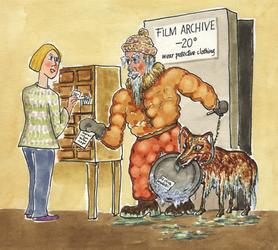
Figure 1. "We must find a better retrieval system, Dogma can't smell the labels in the cold''.
When a film can containing a tightly rolled film is plunged into a cold room the metal can cools to the ambient temperature within a minute or two. The film roll is insulated from the cold can by a tiny air gap, formed by the ribbed structure of the can, by the tiny irregularities between turns of the film and by the loose fit of the roll in the can. It will cool down more slowly, as shown in figure 3. There is relatively little variation in temperature within the film roll, because it has quite a high thermal conductivity, so the entire roll cools down uniformly.
During this period of an hour or two, the cold inner surface of the can will condense water from the air. At the beginning of the process the air will be at, say, 50% relative humidity and at 20°C. Water vapour will condense as soon as the metal can surface falls to 9°C. This temperature is called the dew point. The relationship between dew point, relative humidity and temperature is explained diagrammatically later. There is hardly any water vapour in the air gap but as soon as water vapour is removed from the air it is replenished by evaporation from the warm film, which has a considerable reserve of water absorbed within the gelatin layer, and to a lesser extent in the cellulose acetate base.
There is therefore a continuous transfer of water from the film to the surface of the can. The water will condense first as water, then as ice, and the process will continue as long as there is about a ten degree temperature difference between the can and the film roll. This period can be several hours, depending on the exact situation of the film can in the cold store.
The amount of water transferred cannot easily be calculated, because the water absorbed at the exposed edge of the thin gelatin layer is quickly released. Thereafter the process is increasingly inhibited by the slow diffusion of water from the interior of the roll.
Does this process matter or is it just a theoretical threat? It is easy to find out.
A roll of film was fitted with tiny thermocouples and put in a metal can with a thermocouple attached to its inner surface. The can was put in a chest freezer and its progress towards the freezer temperature was followed.
The thermocouples were type K with wires 0.2 mm thick. The alloys of this thermocouple type have rather low thermal conductivity, which makes them suitable for measuring steep temperature gradients where heat conductivity through the wires to the measuring tip is a source of error. Furthermore the last two centimetres of the wires were placed parallel to the surface of the film to further reduce errors due to heat conduction. One thermocouple was inserted 80 mm from the outer edge of the 260 mm diameter film roll and midway through the 35 mm thickness of the roll. This thermocouple represents the temperature of the bulk of the film roll. A second thermocouple was inserted 4 mm from the circumference and 2 mm from the face of the roll. This gives an approximate temperature for the coolest part of the film roll. The temperature of the inside surface of the steel film can was measured by a thermocouple placed flat against the surface with its last 10 mm sprung against the metal, with no adhesive to disturb the thermal gradient. The air temperature just outside the film can was measured by a fourth thermocouple.
The film roll was considerably smaller than the can, which was 380 mm diameter. The roll was jammed against the edge of the can by two 120 mm rolls of film so that the thermocouple on the inner surface of the can was close to, but not touching the film.
The relative humidity (RH) in the can was not measured. In my experience it is very difficult to measure RH with useful accuracy within a temperature gradient and at temperatures varying over a forty degree range. The film had been preconditioned for several years at 50% RH and 20°C. I used data from Adelstein and co-workers [Adelstein 1997] that shows the equilibrium RH around roll film falling from 50% at room temperature to about 40% at -20°C. The RH at any point can be calculated by assuming that the water vapour distribution within the container is uniform at all times, because the air space is so small that rapid vapour diffusion will ensure homogeneity. The RH at any point within the can is defined by the temperature and RH at the surface of the film roll, modified by the temperature at that particular point. This rather obscure reasoning is clarified with examples later.
The film can was fitted with a window of 1 mm polycarbonate so that the formation of condensate could be observed when the can was immersed in the cold air in a chest freezer. The arrangement is shown at the left of figure 2. The position of the film within the can is shown by the broken white circle. The arrow beside the window points to a subtle detail of the experimental arrangement: before the lid was put on a single fingerprint was applied to the inside of the polycarbonate window from a not recently washed finger.
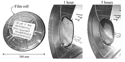
Figure 2. Condensation inside a metal film can is visible through a small polycarbonate window. The entire can is shown on the left. The broken white circle marks the circumference of the film roll within. The arrow points to a fingerprint on the inside of the window. The middle picture shows the situation after one hour in a cold box at -25°C. There is ice on the window opposite the film roll and on the fingerprint, which is slightly hygroscopic because of salts from sweat. On the right is the situation after five hours. The ice is evaporating and the water vapour is being re-absorbed into the film. The process is not so fast where there is no film close by to absorb the water vapour, as shown by the persistent ice on the fingerprint.
Figure 3. The rate of cooling and subsequent warming of the film can. The continuous lines show the course of the cooling process. The broken lines show the warming process when the can is lifted out of the cold box. These warming lines are inverted to allow direct comparison with the cooling curves. These values should be read against the inverted scale on the vertical axis. Notice that the temperature at the edge of the roll is not much different from the temperature deep in the mass of the roll. The can cools very quickly, as shown in the inset with stretched time axis. The slowly cooling mass of the film creates a temperature gradient confined to the air space between film and can. This causes efficient transfer of water from the film to the inner surface of the container.
The film can was put in a domestic chest freezer. The course of the cooling is shown with solid lines in figure 3. The two highest lines are the temperatures within the film. These lines are so close together that one can assume that the thermal conductivity within the mass of film is high compared with the thermal conductivity of the still boundary layer of air at the surface of the film roll. The film can be considered uniform in temperature, with the entire temperature gradient confined to the narrow air spaces between the roll of film and the metal container.
After one day the film can was removed from the freezer and allowed to warm up unprotected. The course of the warming is shown as broken lines in figure 3. These lines are inverted, with a corresponding inverted scale on the axis, so that warming is represented by a falling line. This rather confusing trick is to show that the course of warming is not much different from the cooling pattern. The initially steeper rate of warming is due to the heat released by the abundant condensation of ice on the outside of the can immediately after removal to the warm room air. The slower rate that sets in after about thirty minutes can be attributed at first to the melting of the ice and later to the slow evaporation of the melt water. Both of these processes absorb heat and slow the progress to room temperature. These are minor complications in a pattern that shows the essential symmetry of the cooling and warming processes.
At the beginning of the cooling process, the air close to the surface of the film will have a moisture content which depends on that of the film. The film was equilibrated to 50% relative humidity (RH). If we suppose that the film is at 20°C one can read from the standard psychrometric chart, or Mollier diagram, that the air at the surface will contain 8.6 g/m3 of water, equivalent to a water vapour partial pressure of 1167 Pascal. An approximation to the psychrometric chart is shown in figure 4. I will use vapour pressure units in the rest of the discussion. The water vapour concentration is proportional to the water vapour partial pressure. One must not imagine that the water vapour is exerting a pressure in the everyday sense: all water movement is by diffusion or by flow of the water molecules entrained in a convective air stream.
The temperature at the inside surface of the metal drops quite quickly to -5°C. It shares the same air space as the film, so the water vapour concentration should be the same at its surface as at the film surface, because water vapour molecules diffuse rather quickly through the confined space. But that water vapour concentration is not possible, because the maximum possible concentration in air at -5°C is 3.4 g/m3 (400 Pa). The excess water vapour will condense as ice on the metal surface. Figure 2, centre, shows ice deposition on the inside of the polycarbonate window. The presence of ice signals that the relative humidity at that surface is 100%.
If we now turn our attention back to the film, which is still only a degree or so below 20°C, the RH of the air at its surface should have dropped, to about 20%. The film can is acting as a dehumidifier - withdrawing water vapour from the air and locking it up as ice. The surprisingly low RH calculated for the surface of the film is a consequence of the steep rise in the saturation partial vapour pressure of water vapour as the temperature increases towards the surface of the film. The RH is the ratio of the actual vapour pressure, 400 Pa, to the saturation partial pressure at the surface of the film, which at 18°C, is 2054 Pa.
This low RH is far from equilibrium with the water content of the film, which has hardly changed from its starting value, because there is a lot of water in the film, compared to the relatively small amount of ice that has formed, while the water content of the small volume of air in the can is negligible in comparison to both. The film will therefore release water vapour into the air at its surface, to restore the RH to nearly 50%. This air will then diffuse away to the surface of the can, depositing more ice.
This distillation process will continue as long as the equilibrium water vapour concentration at the surface of the cooling film is greater than the maximum possible vapour concentration at the surface of the can.
This limit can easily be calculated, or read from figure 4. The equilibrium RH at the surface of the roll of film will fall as it cools, from 50% at 20°C to a little under 40% at -25°C. This is plotted as the lower solid curve in figure 4. We now search for the point on this curve where the water vapour pressure is the same as that at the surface of the ice. Since the water vapour concentration is assumed to be uniform everywhere in the enclosure we need only draw a horizontal line from the point defining the vapour pressure over ice at -25°C (64 Pa) to the curve defining the vapour pressure over the surface of the film. The point of intersection is at -17°C, with the film at about 38% RH.
Figure 4. The variation with temperature of the saturation water vapour pressure over water and ice (upper solid curve) and the actual, unsaturated vapour pressure over film conditioned to 50% RH at room temperature (lower solid curve).The broken lines show the vapour pressures corresponding to 80%, 50% and 40% RH, based on the vapour pressure over water, supercooled below zero degrees. The vertical vapour pressure scale is also a concentration scale, so that as air diffuses from the surface of the film towards the cooler can it follows a horizontal path on the diagram, because it cannot obtain, or release water vapour during the journey across the gap. Where this horizontal line hits the saturation curve, condensation will occur. Three horizontal lines show that for film pre-equilibrated to about 50% RH at room temperature the can must be 11 degrees cooler than the film for condensation to occur. At lower temperatures the temperature difference required for condensation is slightly smaller, but a six degree difference in temperature should always be safe for film conditioned to a moderate RH. The vapour pressure curve for ice slides downwards to cut the 80% RH curve at about -20°C. This means that film at equilibrium with this high RH will suffer damage from ice crystallisation.
The movement of water vapour from the surface of the film to condense first as water, then as ice on the inner surface of the can will therefore continue from soon after the film can is put in the cold chamber until the film has cooled to -17°C. One can put the matter in another way: if the temperature difference between film and can exceeds about 10 degrees at any time, there will be condensation. This temperature difference for causing condensation applies approximately at all temperatures between 20°C and -30°C. Figure 4 shows the nearly parallel trajectories of the vapour pressure curve for water and ice (the higher solid line) and the vapour pressure at the surface of film that has been equilibrated to 50% RH at room temperature. The horizontal arrows show the course of the cooling process for the air diffusing from the warm film at three points in the cooling process. The lines are horizontal because the air has a constant water content, meeting no source, or absorber of water on its journey. Where these lines hit the saturation vapour pressure line, condensation will occur. The lines vary from 11 degrees long at room temperature to 8 degrees long at -10°C. The smaller temperature difference required for condensation at the lower temperature is due to the lower saturation vapour pressure over ice compared to water at the same temperature. This is a minor detail. The point is that if the temperature difference between can and film is never greater than about six degrees, there is no risk of condensation.
This rule of thumb applies to film at equilibrium with 50% RH. Moister film will cause condensation at a smaller temperature difference. In very moist film, ice will even form within the film on cooling. The 80% RH line intersects the vapour pressure curve over ice at about -20°C. This means that moist film at equilibrium with over 80% RH at room temperature will form ice crystals within itself on cooling below -20°C. This divergence in the vapour pressure over ice and over supercooled water looks unimportant on the graph but indicates a considerable danger during the later stages of the cooling process.
Once the can of film has attained temperature uniformity, the water in the ice that is formed on the inside surface of the can is reabsorbed into the film. The RH over the ice surface is by definition 100% and the film will assert a RH close to its surface of about 40%, depending slightly on how much water it has lost to the ice deposit. Since the temperature of ice and film are now the same, it is the relative humidity gradient that defines the water vapour concentration gradient, which is now in the opposite direction. The water will therefore diffuse back into the film. The disappearance of the ice after just a few hours is shown on the right in figure 2.
The formation of ice is therefore a transient phenomenon which causes no damage to the film, as long as the ice and the film are separated by air. In practice, however, the geometry of the system is more complicated: at some points the film will touch the metal, keeping it warmer. At these points the water vapour may condense as water for a considerable period, and be absorbed by capillarity into the turns of the film roll, causing local wetting. Later in the process this water will freeze within the film, with consequent physical damage through the growth of ice crystals.
One might ask why the ice, as it evaporates from the can, does not reform as ice at other places within the film. Maybe it does, sometimes. This experiment is not nearly detailed enough to test the theory but in principle it is possible to generate ice crystals within the film roll. Suppose that the film roll is not uniformly wound, so that there are small gaps, like slightly parted lips, between the turns of the roll. Here the water vapour has easy access, so the local RH can approach 100% though it will never quite reach that value. But even 80% RH will cause ice crystals to form within the film, as described above.
There is even a small chance that ice will form in the extreme outer surface of the film roll, where the edge of the gelatin is exposed. I have heard no reports of fraying of the edge through repeated freeze-thaw cycles, but I'm not sure that anyone has looked. In the end, however, as the film comes to equilibrium throughout its mass, ice will disappear. This is because the water in the film, now in equilibrium with 40% RH, is not in a form that can crystallise as ice. Ice forms when water molecules take up a certain orientation to each other to form the solid lattice. Water molecules in the film are individually bound to atoms in stiff polymer molecules. They are believed to jump frequently between absorption sites but they do not clump together and reorient themselves to form ice crystals, because this process requires more energy than the absorption of separated water molecules on the polymer chains.
At this point the reader will be thinking that this is just another academic exercise without any significance in practice. No-one has reported damage from rapid cooling of film, so why worry? My point is that the damage will not be of the sort that is easily noticed. Condensation in film stores, as in buildings, causes damage precisely where there is inhomogeneity in the structure. That is why I added the fingerprint: even handling the film, or the can, with sticky fingers can provoke accumulation of considerable amounts of water concentrated in one area. The salts in sweat not only absorb water from the air but also reduce the freezing point of the solution below zero.
Condensation as ice on the can is usually harmless, and the theoretical risk of ice formation within the film during the last stages of cooling is not proven, but water can condense if parts of the can are cool but above zero degrees for some time; for example, where several cans are put together into the cold room, or where the contact with the warm film is fairly close, as described above. One can imagine that the experiments of scientists testing the damage done by exposure to cold will miss examples of local damage, precisely because they are so careful to make a perfect experimental setup. In any case such damage will only be visible as blemishes that flash by too quickly to be properly seen when the film is projected, or copied.
Condensation on cooling can be prevented by making the film container of a moisture absorbent material such as cardboard. This will absorb the water vapour from the warm film, so that the RH at the cold surface never reaches 100%. Unfortunately, this solution just pushes the moment of danger over to the warming up process. The warm, moisture absorbent box will then take over the role of the film in the previous scenario: releasing water vapour to maintain 50% RH in the warm air at its surface. This moisture will then condense on the cold roll of film, first as ice on the surface, which later melts and runs into the capillaries of the film roll. This is a much more devastating process, all the more efficient because cardboard releases water vapour much more readily than the tightly wound film, where water vapour only exchanges through the thin strip of gelatin exposed at the edge of the film.
Thermally insulating boxes are not a reliable solution. The inside surface of the box will be warmer, but the time this surface is above zero degrees will be longer, with a consequent risk of water condensing and moving into the film.
However, a can in which the gap between itself and the film is filled with an absorbent material which is also insulating, should entirely stop condensation. This is because the amount of water transferred from the film to the can is very much reduced if convective streaming of the air is prevented.
The space could be filled with leaves of crimped paper which provide a softly elastic gap filling substance which still has tiny air pockets to provide thermal insulation. The paper will slow down the diffusion of water vapour both directly, by preventing convective streaming, and by itself absorbing water to buffer the transfer process. The dramatic improvement that can be expected from such a change in film containment is suggested by a second experiment.
The inhibiting effect of layers of absorbent material on vapour transfer was demonstrated with the experiment shown in figure 5. A stack of sheets of paper was placed between two copper plates at different temperatures and the moisture movement was followed by weighing the paper sheets.
The thermal mass of the warm film roll is here represented by a substantial water container, initially at 20°C, but cooling fairly rapidly to zero degrees. The temperature then remained at zero for the rest of the experiment, due to the slow freezing of the water. The water container rested on a copper plate which settled to a steady -6°C. Directly under the plate is a sheet of paper, which, like film, contains substantial water content in equilibrium with 50% RH, its initial state. This sheet represents the exposed edge of the film, with its exchangeable water in the gelatin layer. Between this sheet of paper and a second copper plate held at about -22°C were a further approximately 100 sheets of paper, with a total thickness of 16 mm. Thermocouples were distributed equally through this mass of paper, and also some sheets were treated with dry methylene blue powder to detect the presence of water during cooling, or during subsequent warming to room temperature (the grey methylene blue particles dissolve to give an intense blue stain). The entire assembly was lowered into a chest freezer where the lower copper plate rested on an aluminium finned heat sink frozen into a eutectic mixture of 55% polyethylene glycol in water, which has a melting temperature at about -18°C. In fact, the heat flow through the paper was too small to cause the heat sink to reach this temperature.
Figure 5. Experiment to measure water vapour diffusion through layers of paper between two surfaces at different temperatures. The tray at the bottom is filled with a eutectic mixture of polyethylene glycol in water. A finned aluminium heat sink is immersed in this frozen mixture at about -25°C. A copper plate, 25 cm square is placed on the heat sink. 100 sheets of paper are piled on this plate. Five groups of five sheets each were weighed before the experiment began. These groups are distributed evenly throughout the pile, with thermocouples to measure the temperature at the same points. This pile of paper sheets is surrounded by a guard ring of paper sheets, to ensure a uniform temperature and moisture gradient perpendicular to the copper plates. Single sheets of paper dusted with methylene blue dye are inserted just below the weighed sheets to test for liquid water during cooling or after warming. The warm side of the assembly is provided by a polyethylene box nearly filled with water, which sits on the top copper plate. The dimensions and quantities are such that the freezing water in the box keeps it at zero degrees for two days, after a short initial cooling from room temperature. The entire assembly was set in a chest freezer. After 24 hours the weighed pieces of paper were removed, sealed in plastic bags in the cold, and then warmed up before re-weighing.
After 24 hours of exposure to this constant 16 degree temperature gradient, there would have been condensation on the lower copper plate if there were just air between it and the one layer of paper stuck to the upper plate. With the stack of paper in place there was no reaction from the methylene blue condensation detector. Selected pieces of paper were removed from five positions within the stack, put into sealed polyethylene bags, warmed and weighed in the bags. The weight loss in the uppermost piece of paper was equivalent to a fall in equilibrium relative humidity around it of just 3%. Correspondingly the lowest piece of paper, in contact with the lower copper plate, had gained water equivalent to a 2% rise in RH in the air within it. There was therefore no danger of condensation on the colder plate, representing the film can.
The reduction in water vapour transport through the paper stack can be regarded as analagous to the reduction in heat transfer through an insulating layer. The vapour must move by diffusion across the tiny air spaces, a process that is much slower than convective flow. The experimental setup was thicker than is practical in a film can, for experimental convenience and precision. However, one would expect that a much thinner paper stack would provide sufficient protection to cooling film.
| Table 1: Equilibrium relative humidity change within the paper stack | |||||
| Temperature oC | -6 | -10 | -14 | -18 | -22 |
| Relative humidity change % | -3.1 | -1.0 | -0.4 | +0.1 | +2.0 |
The extraordinary effectiveness of an absorbent, porous interlayer which entirely fills the gap between the warm and the cold surfaces, suggests that a minor change to film can design would allow film to be tossed into the cold store with no intermediate conditioning at all. Removal from the cold store could also be brutally quick, without any danger. One must appreciate that this system works because there is no air space big enough to allow convective flow of air, and there is no space big enough that there can develop a more than 10 degree temperature gradient across it. A simple wrapping of the film in tissue paper before putting it into the can is not enough, and can cause serious condensation, because of the very easily exchanged water content of the paper and the uncontrolled geometry of the air spaces. The absorptive, reasonably insulating lining must be both uniform and springy so that it embraces the film roll without significant air pockets.
Until such a containment system is developed and tested, the reliable solution is to slow down both the cooling and the warming processes, so that there is never more than six degrees temperature variation anywhere in the mass of materials. It is not so easy to establish rules for the safe handling of batches of materials that can vary from a single negative to a wagon load of multi-reel movies. I suggest that the clumsiest but probably the most reliable method is to move all material through a conditioning lock, where all materials, regardless of bulk, are slowly cooled or warmed at a pace that is safe for the most massive conceivable package.
This advice only applies to film that is in equilibrium with less than 60% RH. If the film has a high water content, the cooling has to be done even more slowly. Film that one suspects is over about 80% RH equilibrium should not be put into the cold store. It will suffer damage even if it is cooled and warmed very slowly. The danger is not averted by slow cooling: at this water content ice crystals will form within the gelatin layer. Such film should first be dried to about 50% RH at room temperature.
The next question is: how does one measure the equilibrium RH around a roll of film that has just been shipped in from being copied or shown? A simple but adequate way is to put the film in a fairly well fitting polyethylene bag together with a paper relative humidity sensor of the dial type, with a display bold enough to be read through the plastic. An electronic RH sensor can also be used and will respond quicker. The sensor should be close to the flat side of the film roll. After an hour at a constant room temperature the reading of the sensor should be reasonably stable and sufficiently accurate, though not quite at its final equilibrium. Take care that there is not a strong light on the bag, because this can cause temperature gradients that disturb the moisture equilibrium.
Both paper and electronic humidity sensors are notoriously unstable and need calibrating about every six months. If all this seems rather tedious one can draw the conclusion that film should hardly ever be moved in and out of cold storage: a program of copying for showing will reduce the strain on both film and archivist.
Karen Brynjolf Pedersen prepared the experiment with the paper moisture buffer and Yvonne Shashoua photographed the ice growing within the can.
Adelstein,P.Z., Bigourdan,J.-L., Reilly,J.M., 1997. Moisture relationships of photographic film, Journal of the American Institute for Conservation, Volume 36, Number 3, 193 -- 206
This article is included in the Proceedings of the Conference: 'Preserve, then Show', sponsored by the Danish Film Institute and due for publication in the autumn of 2002. It is published on the web by permission of the Danish Film Institute.

This work is licensed under a Creative Commons Attribution-Noncommercial-No Derivative Works 3.0 License.